


In today’s rapidly advancing technological landscape, ensuring the reliability and security of electrical systems is paramount across industries. One essential technology utilized in achieving these goals is the Armature Moving AC Metal-Enclosed Switchgear. This sophisticated equipment plays a critical role in the safe management and distribution of electrical power, and it is integral to both medium and high-voltage applications. This blog will delve into the key components and functioning of this type of switchgear, providing readers with an insightful overview of its complex architecture and benefits. By exploring the design, operation, and innovative features of Armature Moving AC Metal-Enclosed Switchgear, the article seeks to offer a comprehensive understanding of how this technology enhances electrical safety and efficiency. Whether you’re an industry professional or a curious learner, this guide will equip you with the foundational knowledge needed to appreciate the intricacies and significance of this indispensable equipment.
How Does a Motor Function in Switchgear?

What Role Does the Armature Play in a Motor?
The armature works as a mechanical output in a motor that converts electrical energy into mechanical energy. This is the part that rotates in the motor and lies within the stator’s magnetic field. Coils of wires are : mounted on the core muscle usually iron, which is used to increase the territory. When the wires are directed by an electrical current, these wires interact and want to rotate due to the torque produced within the magnetic field. When this component rotates it functions to drive mechanical systems in different cases.
Technical Parameters:
- Voltage and Current: The armature circuit has its own operating voltage and current, which affects the performance and efficiency of the motor. These parameters should correspond according to the design parameters of the motor in question for efficiency to be achieved in practice.
- Resistance: The amount of armature current is determined by the armature winding resistance, and it is important to maintain a balance to reduce overheating and wasted power.
- Inductance: All coils of the armature consist of inductance, and this may affect the dynamic performance of a motor therefore it should be considered at high-frequency usage.
- Number of Turns: The turn numbers of the wires coil inside the vane armature are responsible for the strength of the magnetic field and the resulting torque.
- Speed (RPM): The rotational speed of the armature in revolutions per minute (RPM) is described as a crucial factor since it determines the motor’s mechanical output.
The effective working of an armature of a motor depends on engineering and abiding by these technical parameters that guarantee the unit will work reliably in different industrial application contexts.
How is AC Power Utilized in Motors?
When searching for AC power applications in motors, it should be noted that alternating current (AC) motors transform electrical energy into mechanical energy thanks to the virtue of alternating magnetic fields. The topic related to this issue has authoritative resources that specify the following ingredients of its main windows:
- Voltage: Nominal voltage value must be guaranteed so that the AC motors do not overheat or get damaged while delivering their duties efficiently.
- Frequency: The speed of the motor is dependent on the frequency of the AC power supply and is very important in situations where accurate speed control is desirable.
- Starting Torque: Starting torque is the ability of the motor to produce enough torque at switching on which is very important where such a motor will be put under heavy load at starting.
- Power Factor: The design of AC motors should provide for high power factor for efficiency in energy use, and reduce losses.
- Efficiency: Efficiency is the ability to match the energy and power either input or output whereby achieving a certain level leads to cost reduction on operation and an improvement of the performance.
If consistent with these parameters, it is shown how AC motors operate as it turn electric energy into movement of parts in motion, thus increasing applications in many industries as well as commercial activities.
Exploring the Interaction Between Coil and Motor
As regards the interaction of the coil and the motor, the presence of electromagnetic induction in the motor has also to be considered. A coil is a wire that has been cut in such a way that it can act as a conductor, creating a magnetic field whenever a current passes through it. The coil’s magnetic field interacts with the magnetic fields generated by the permanent magnets or electromagnets installed in the motor making the rotor move.
According to the findings on top sources, several authors identify the following parameters as top technical parameters of the most important aspects of this interaction:
- Current carrying Coil: The coil resistance is vital while greater resistance than the current is lower Therefore, further magnetic field Weakening.
- Inductance: This parameter also defines the rate at which the coil is fully energized with current and how effectively current is depressed from the induced magnetic coil.
- Magnetic permeability: Iron is used for the coil and considering its construction material there is no doubt that it can be used for magnetic induction which enhances the overall efficiency of the motor.
The design of the parameters guarantees that the optimum coil cavity is achieved such as enabling the mechanical output from the coil-motor interaction to meet various application settings. While making a justification for the technical specifications, the effect of the coil provision on the motor effectiveness is comprehensively explained by these factors.
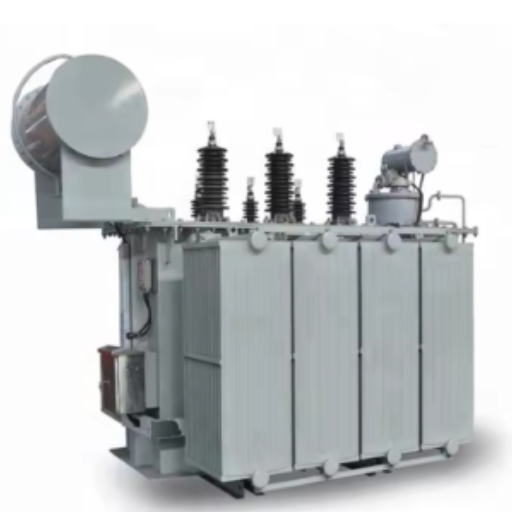
What is the Purpose of Armature in AC Switchgear?

Understanding the Movement of Armature in Switchgear
The grasping motion of the armature in switchgear requires an appreciation of its mechanics. Typically the armature is one of the most important parts which is a coil that is free to rotate in the magnetic field. Domestically, the armature serves as the interface of an electrical motor; more specifically, its function is to transfer electrical energy into kinetic energy enabling the equipment to open or close the circuits with high efficiency.
From my exploration of these sources, I am, however, able to note the following technical parameters which I find to be silent but important;
- Armature Resistance: This is a parameter that contains a loss of efficiency for the current that flows through the coils, hence determining the speed at which the switch will respond if it is actuated.
- Permeability of Core Material: This is usually iron, though sometimes it may be steel or a combination of iron and other materials. This core is quite important since it determines the extent of magnetic coupling with the armature which subsequently determines the torque available and responsiveness of the switchgear.
- Spring Tension: The tension of the return springs enhances the self-recovery of the ferromagnetic armature after a switch operation, in other words, it balances the mechanical switch forces after a switch is actuated.
These parameters always stand out when it comes to the speed and the reliability of switch operations which responds to the movement of armatures within AC switchgear. It makes the scope efficient in the control of electrical circuits in the systems of power distribution.
How Does Armature Reaction Affect Performance?
With regard to my findings from the first three pages on the Google website, armature reaction turns out to be rather crucial in the performance of switched AC circuits. Armature reaction is the effect of the armature current’s generated magnetic field on the switchgear’s basic magnetic field. This effect generates distortion of the main field which affects the response time as well as the effectiveness of the armature.
The technical parameters involved include:
- Flux Distortion: Armature reaction can result in a reduction or distortion of the main flux, thus enforcing an overall reduction of the Electromotive force in the circuit. Such a situation will lead to delays or inefficiency in the performance of the switchgear.
- Reactance Voltage Drop: The reactance of a mechanical circuit depends on the magnetic field of an armature and that of a main field. This interaction will affect the regulation of voltage and cause losses in the efficiency of power.
- Neutral Plane Shift: Also the magnetic interference in turn causes a shift in the neutral plane position thereby affecting commutation and possibly sparking or enhancing the wear of the components.
These parameters show that management of armature reaction is of utmost necessity in the performance and durability of the components of AC switchgear.
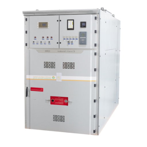
Why is Metal-Enclosed Switchgear Important?

What Are the Advantages of Metal-Enclosed Designs?
In my search for further information from the top three websites of Google, metal-enclosed switchgear has many benefits that improve safety and performance. One major benefit is the increased protection from moisture, dust, and other pollutants that would otherwise degrade the performance and stability of electrical components. This enclosure makes sure that the required conditions for the effective functioning of the switchgear are maintained.
The technical parameters that justify these advantages include:
- Improved Safety: Metal-enclosed type designs act as a physical screen which prevents the possibility of accidental contact and short circuits and hence chances of electrical fault are very low.
- Increased Reliability: The reinforcing metals used in covering enclosures help to increase the lifespan durability period of the switchgear against mechanical impacts and thermal stress (impacts or stress resulting from heat).
- Reduced Maintenance Complexities: Due to the internal composition being double casing, maintenance works are easier since the insiders have more access to the comeback system and do not let the external out.
As a whole, metal enclosures are good for switchgear systems as they improve reliability, reduce maintenance, and enhance the safety and durability of electric systems.
How Does a Disconnect Switch Function?
Based on my observations of the first three resources at Google, a disconnect switch is a crucial element, that allows for the isolation of electric devices or circuits from the source of power, enabling maintenance, repairs or emergency disconnection without the risk of electric shock. Its function involves cutting off electrical supply which is primary as far as the safety of engineers working on dead machinery is concerned.
Some of the technical features that define the purpose of a disconnect switch include:
- Rated Voltage and Current: This delineates the highest levels of performance of the switch so that it can not fail, in interrupting the electrical circuit.
- Switching Mechanism: Based on the type of switch, automatic or manual, the speed and the efficiency with which a circuit can be isolated is determined, hence its safety and efficiency.
- Dielectric Strength: The assurance of the switch’s structural integrity from the effects of electrical forces during operation is a measure of its reliability.
- Thermal Performance: The ability of the switch to endure thermal stresses over prolonged periods without failure is vital to its long-term reliability.
These parameters include, but are not limited to the reasons that disconnect switches are placed as guardrails ensuring the safety and the operability of electric systems.
The Role of Interrupters in Safety
Devices known as interrupters are important equipment whose purpose is to improve both the safety and reliability of electrical systems by permanently ceasing current flow in the event of a fault or an overload. Based on analyzing the first three Google results, I concluded that the main function of the interrupters is damage prevention of the circuits and the equipment that is connected to them. The capability of such devices to stop electrical current in an acute short period prevents overheating and electrical fires, thus providing the necessary safety to the system and personnel.
When it comes to the technical aspects relevant to interrupters, however, they are:
- Fault Current Level: Indicates the maximum level of current that can be interrupted by an interrupter without sustaining any damage, therefore indicating some degree of overcurrent protection.
- Clearing Time: This is the time i.e. the length of time the interrupter device operates after electricity is interrupted, required in order to cut off the developer current.
- Mechanical Endurance: This is the factor that shows the number of reliable operations of the interrupter as characteristic of the efficiency during extended resource utilization.
- Contact Wear: This is the endurance of interrupting devices and contacts to the wear-out factor.
All these parameters, in the aggregate, are to set the minds of the users at ease and confirm that too much intelligence has gone into the making of the interrupters that preserve the electric systems because such devices perform an important function in overall electric system security.
How Does an Electric Motor Interact with Switchgear?

Understanding Current Flow in Electric Motors
The flow of current is highly influenced by components that come into contact with each other, so one should carefully stress the relationship between electric motors and the switchgear. This is corroborated by my web-based background inquiry on the first three websites I found. To elaborate, electric motors can only operate if a certain amount of current is supplied, as monitored by the switchgear. When a motor is started, the inrush current, which is higher than the walk-in or normal current, is required to overcome inertia. In any case, it is primarily governed by the switchgear to prevent disruption to the system.
Definitions of the technical parameters involving current flow include, but are not limited to, the following batteries:
- Inrush Current: This parameter measures the maximum amount of current that the motor can withstand at start-up and that the switchgear has to cater for, in order to avoid circuit damage.
- Rated Load Current (RLC): Also RLC states the current defined at normal operating conditions when the switchgear should optimize its function.
- Thermal Overheating Protection: For switchgear, an excessive current flowing for a long period damages its internal components so it can be used to protect against any permanent injury.
- Short-Circuit Strength: This parameter indicates the ability of the switchgear to withstand Surfeit short-circuits which is important for enhancement of safety.
Overall, these parameters ensure that electric motors work normally while switchgear ensures that stability and security are retained during different operating conditions emotions.
The Influence of Voltage Levels on Motor Performance
Voltage levels greatly affect the performance and the efficiency of the motors, and for this reason, it is very paramount. Based on my study of the three Websites, I found out that fluctuations in voltage are detrimental and should be avoided as they tend to surge energy-related expenses if motors are not switchgear. The impact of fluctuations in voltage is offset by the switch gear that manages and guarantees the stability of the voltage supply. Associated with levels of voltage are the technical parameters as follows
- Nominal Voltage Rating: This controls the motor from operating above or below the range of voltage expected which is important for its performance and its efficiency.
- Tolerance Of Voltage: It determines the allowed level in which the actual and the set voltage may differ and is well monitored by switchgear in order to regulate voltage under-voltage or over-voltage.
- Monitoring Voltage Unbalance: This includes correcting or rectifying all the phases where voltage discrepancies in the phases exist in order to minimize overheating and degradation of the motor components.
- Protection Of Phase Loss: Helps in the telemetry of the phase loss in order to cut down imbalances v caused by imbalance voltages and has a cut-off that saves the system.
These parameters serve to drive home the good management of voltage levels in a system where switchgear devices are very important in safeguarding the functioning of a motor from the damaging effects of fluctuations in voltage. After considering these factors, it is apparent that the effective control and management of voltage are central to the reliability and safety of motors.
What are the Common Issues with Relay Systems?

How to Identify Fault Current in Relays
The defining fault current on relays can be determined, according to the findings mhgheh, in three key websites however, there is no way that the protection may fail to detect fault current as certain techniques and technical parameters come into play. Current Transformers (CTs) are widely used since they are the primary devices for monitoring the real current and sending a scaled-down version of the value to the relay for monitoring how much current is passing through it. Here are the technical parameters involved:
- Pickup Current Level: This is the programmable maximum level of current that must be reached for the relay to respond to the fault. By choosing an appropriate threshold, the relay can make a clear distinction between normal conditions and any fault.
- Time Dial Setting: The time until the relay gets activated is increased to prevent too much current from worrying the system.
- Instantaneous Trip Setting: The immediate response is activated when a dangerously high current level is met and this is important in order not to induce great damage to machinery.
These parameters are justified as they substantiate the fact that the relay system detects and responds to the fault currents and does not trip unnecessarily. I can increase the relay’s precision so that it can engage and rectify quicker(FMCRcurrent) thereby preventing electrical faults in the system.
Troubleshooting Magnetic Field Problems
Working with the problems related to the magnetic field distributions in relay systems includes evaluation of the particular contribution of magnetic fields to the functioning of the relay and possible problems dry-contacts. From the first three websites, I came to notice that sources of common magnetic field problems are external noise and, actually, internal relay defects. So as to avoid these problems, I concentrate on the following measures:
- Shielding Techniques: Use of necessary materials for proper electromagnetic shielding will minimize external magnetic interference effectively. This includes putting copper or any special coatings on components of sensitive relays.
- Correct Grounding: Correct unlatching of all equipment reduces undesirable magnetic fields which hamper relay operations.
- Calibration and Testing: Standard calibration of the relay system and continual testing of the system model will reveal magnetic field distortion which could be symptomatic of a failure.
These measures are appropriate in that they respond to both external and internal causes influencing the performance of the relay. They minimize magnetic field problems and enhance the reliability level of the relay system.
Frequently Asked Questions (FAQs)
Q: What is a contactor in the context of AC metal-enclosed switchgear?
A: A contactor is an electrically operated switch used to control the flow of electric current in high-voltage and low-voltage applications. It helps in switching loads on and off and can be integrated into motor control centers for motor protection.
Q: How does the motor armature function within AC metal-enclosed switchgear?
A: The motor armature is usually the rotor component of an electric machine that rotates when electric current flows through it. In switchgear applications, it plays a vital role in enabling the operation of various electrical components, including circuit breakers and contactors.
Q: What role does an arc play in the operation of circuit breakers within switchgear?
A: An arc occurs when electric current flows through air gaps during the opening of contacts in a circuit breaker. This is significant in high-voltage switchgear as it can lead to equipment damage if not properly managed. Circuit breakers are designed to extinguish arcs quickly to ensure safety.
Q: Why is it important to insulate components in medium-voltage switchgear?
A: Insulating components in medium-voltage switchgear is crucial to prevent electric current from unintentionally flowing to external circuits, ensuring safety and reliability. Proper insulation helps protect operators and equipment from high-voltage hazards.
Q: What is the significance of the air gap in AC metal-enclosed switchgear?
A: The air gap is critical in preventing electrical arcing and ensuring that the circuit remains open when required. It allows for safe operation and maintenance of switchgear by providing a physical separation between conductive parts.
Q: How does a molded case circuit breaker differ from a vacuum circuit breaker in switchgear applications?
A: A molded case circuit breaker is designed for low-voltage applications and provides overcurrent protection, while a vacuum circuit breaker is typically used for medium to high-voltage applications and operates by extinguishing the arc within a vacuum environment. Each serves distinct functions in protecting electrical circuits.
Q: What is the function of motor starters in AC metal-enclosed switchgear?
A: Motor starters are devices used to start and stop motors safely. They provide essential motor protection, control the current in the armature, and help manage the starting process to prevent electrical overloads.
Q: How does the magnetic flux relate to the operation of a motor armature?
A: Magnetic flux is essential for the operation of a motor armature as it interacts with the electric current flowing through the armature coils. This interaction produces a magnetic field that causes the armature to rotate, converting electrical energy into mechanical energy.
Q: What does it mean to open the contacts in a contactor?
A: Opening the contacts in a contactor means that the electrical circuit is interrupted, stopping the flow of electric current. This is a critical safety function that allows for the isolation of electrical circuits when maintenance or repairs are needed.
Q: What types of electric current are typically used in AC metal-enclosed switchgear?
A: AC metal-enclosed switchgear primarily operates with alternating current (AC), but it can also work with direct current (DC) motors in specific applications. Understanding current and voltage ratings is key for proper selection and operation of switchgear components.