


In electrical engineering transformers have a prominent place and function by supporting electricity transmission, converting voltage, and changing electric energy into required forms. Without these devices and their extensive functions, devices of a commercial and industrial nature would be impossible starting from the basic power supply networks and ending with the complicated power supply of instruments and devices in medicine. This article intends to offer an orderly depiction of the major sorts of transformers along with their types and functions, core components and the types of applications that they can serve. This automatically implies that the existence of such classifications is important as far as it exposes the reader to some of the features and functions of different types of transformers allowing appreciation of their engineering and practical relevance.
What are the main types of transformers based on their function?

Transformers can be classified into several major types based on their role:
Power transformers – These are transformers used in transmission networks to step up or down the voltage level to ensure that power is transmitted over long distances efficiently with minimum loss of energy.
Distribution transformers – These are found closer to consumers and serve the purpose of lowering the voltage to appropriate levels for use in residential, commercial, or even industrial areas.
Autotransformers – These are voltage transformers which are circular in design having single winding which acts both primary and secondary together. It is capable of high efficiency in providing small variances in voltage.
Instrument transformers – This section contains.
Current transformers – CTs – instrumentation and meter current inputs measurements that would exceed several thousand amperes by CT current sensors to lower proportions that are appropriate for the measurement instruments.
Potential transformers – PTs – transformers that are designed specifically for high voltage transforming procedures to ensure accurate voltage readouts of the system’s monitored parts.
Isolation transformers – the type of transformer that serves the purpose of preventing direct contact between electrical circuits and is mostly used as a safety measure and an electrical noise reducer.
Every one of these categories has a different function and it is one of the most important aspects that allow electrical systems to operate reliably and efficiently in different areas of their usage.
Power transformers: The backbone of electrical grids
Power transformers are considered the backbone of electricity grids as they allow the transfer of power over long distances relatively easily. A transformer’s primary function is to increase or decrease voltage to minimize the amount of energy lost during and after the transmission of electric power. These kinds of transformers work on the principle of electromagnetic induction and consist of a primary and secondary winding around a magnetic core.
In general, power transformers are classified as step-up and step-down transformers. The step-up transformer is used in generation stations and increases voltage levels for long-distance transmission whereas step-down transformers are used in substations to reduce the voltage to residential, commercial or industrial levels. Owing to the structure of the transformers, their operation is highly efficient with most achieving above 99% efficiency, which assists in reducing waste of resources.
Owing to the power transformers’ application to the grid, they need to be reliable therefore necessitating strong insulating materials, oil or air cooling systems, and constant maintenance to avoid overheating, insulation failure, and a variety of other issues. Other issues that arise include changes in the load, aging of the components, and exposure to the environment. Thankfully, newer technology such as sensors or smart monitoring reduces the issues greatly and provides a stable grid that can be relied on.
Distribution transformers: Bringing power to neighborhoods
Distribution transformers are essential in ensuring power is supplied to remote areas with a low population density with great precision. This is achieved through stepping down the voltage of the primary distribution lines. Such transformers carry key technical parameters, among which are the following:
Voltage Rating: Primary voltage utilised can range between 11 kV, 13.8 kV and 33 kV secondary voltage does commonly operate at 400 230 V for domestic purposes.
Power Rating: The range is broad, spanning from 5 kVA and reaching 5000 KVA, as the load puts the most demand on the device.
Impedance: This usually runs between four and eight percent ensuring short circuit and voltage regulation levels are within legal limits.
Efficiency: There ought to be reduced losses of 98% and above which by extension should improve performance levels.
Cooling Method: Most of them depend on the application and location and therefore can be ONAN which is Oil Natural Air Natural or air cooled.
Insulation Class: Standard insulation which is rated as Class A, B, or F is thermal limits and insulation can work in such volatile conditions.
In every distribution transformer, energy losses are very low and power delivery is optimal. This has been the case through routine maintenance such as thermal imaging and maintenance on the oil properties. Every single transformer output can be relied on due to these parameters.
Instrument transformers: Precision measurement in electrical systems
Transformer вставка name units fall and maintenance systems with all high requirements security UTE in net energy source for acceptance installation systems monitor. Isolation of measurement devices from high-energy circuits creates conditions for reliable monitoring systems and maintenance of their function. Current transformers CT and voltage transformers VT are complemented by other types of transformers and manufactured to fulfill requirements for power grid and industrial systems.
How do step-up and step-down transformers differ?

The basic difference between the step-up and step-down transformer is its use and type of winding arrangement. A step-up transformer raises the voltage from the primary side to the secondary side since the number of turns in the secondary winding is greater than the number of turns in the primary. This is typical of power transmission where one wants to reduce energy losses over long distances. A step-down transformer on the contrary lowers the voltage since in a step-down transformer the secondary winding has less number of turns than the primary winding, in most cases the step-down transformer is used in distribution systems to make the usable voltage level safe for the end user. Both types employ the concept of electromagnetic induction and play critical roles in the delivery of power in a viable and stable manner.
Step-up transformers: Increasing voltage for efficient transmission
Step-up transformers are unique electrical devices that perform the function of boosting voltage levels to reduce power losses when electricity is transmitted over long distances. The design of these types of transformers is such that the primary winding has a lesser number of turns than the secondary winding, which increases the output voltage and decreases the current by the laws of electromagnetic induction. The increase in voltage level results in a lower amount of current passing through transmission lines hence less amount of resistive losses (I²R losses) is incurred thus making the power transmission system more efficient. Because of their importance, step-up transformers are more used in power generation plants to raise voltages to the level within high voltage transmission networks so that electricity may be transmitted across long distances optimally.
Step-down transformers: Reducing voltage for safe consumption
A step-down transformer works to reduce the voltage of the electricity coming from the transmission lines which can go to as high as 1000 kV and on the receiving end’s equipment is usually designed for a voltage supply of 120 V or 240 V depending on the region. It would be quite inconvenient and unsafe to use the appliances designed for the standard voltages at such high voltages, and these transformers help in increasing compatibility. Reducing voltage is done by changing the turns ratio of primary and secondary windings inside the transformer. Without these step-down transformers, the integration of long-distance transmission networks would cause many catastrophic safety issues.
Applications of step-up and step-down transformers in power systems
In the electrical power system, step-up and step-down transformers have their respective roles in the supply, transmission, and distribution of electricity.
Step-Up Transformer
At the electrical generation stations, the step-up transformers are used to increase the output voltage of electricity. Higher output voltages such as 110KV, 220KV or 765KV can be achieved depending on the needs such transmission greatly reduces the loss of energy primarily caused by resistance within the conductors. High voltage means that the same aimed power will require less current the losses will be at a minimum.
Step-Down Transformer
Transformers that step down high transmission voltage to a much safer limit which can be safely used by the end users and applied to other uses are the step-down transformer. For Example:
Transformers at substations step down the voltage from transmission voltage levels (110kV or 220kV) to distribution voltage levels (11kV or 33kV).
Transformers further reduce the voltage to the levels required by the consumers, 120V/240V for household or business use through Local Distribution Transformers.
All types of transformers help maintain the stability of the system, reduce losses of energy and improve the safety of operational systems which are important in ensuring the uninterrupted flow of electric power throughout various interconnected power systems.
What are the various types of transformers based on core material?
Transformers can be characterized by the core material employed in their construction, which in turn affects their efficiency, operation and application as follows:
Iron Core Transformers
They utilize laminated iron cores to minimize eddy current losses and are extensively utilized in power and distribution systems owing to their high efficiency and long-lasting nature.
Ferrite Core Transformers
These are lightweight, high-frequency operational transformers with ferrite materials thus suited for electronics and telecommunication applications.
Toroidal Core Transformers
They have a ring-shaped core made of materials such as iron or ferrite and are identified as transformers with low electromagnetic interference and high efficiency, hence are used in different electrical equipment of very high sensitivity.
Air Core Transformers
Since they do not utilize a magnetic core, they use an air medium as a core and are specific to high-frequency operation, though less efficient than the magnetic core transformers.
Each type is designed with particular operational characteristics and thus finds use in various electrical systems.
Iron core transformers: Traditional and efficient
Iron core transformers function by making use of a laminated iron core which minimizes energy losses that are associated with eddy currents thus improving efficiency greatly. Due to their improved efficiency, these types of transformers find application in electric power distribution systems, industries, and electrical machines which require high power levels with reduced losses. The insulation coating on the laminations in the core minimizes excessive heating and magnetic hysteresis. Such structures guarantee the reliable operation of the transformer, even with heavy loads. In addition, the design allows for strong magnetic coupling between the primary and secondary windings, allowing the majority of the applications of AC and DC electrical circuits.
Ferrite core transformers: High-frequency applications
Transformers that use ferrite cores are constructed to work efficiently under high-frequency ranges of more than 10 kHz to 100 MHz. Ferrite, which is made from iron oxide along with metallic compounds such as manganese and zinc, forms the core of this transformer. This optimization gives the transformer a reasonably high magnetic permeability without high conductivity hence minimizing eddy currents at all times.
The key metrics for ferrite transformers are as follows:
Frequency Range: The frequency is determined by its usage and the medium of operation between 10 kHz and 10 MHz.
Core Loss Density: Self-induced current below 300 Mw/cm cubed at 100 kHz and 200 mT.
Saturation Flux Density: The estimated values for NHF65-75R and NHF60-120N are in the range of 0.35 T and 0.5 T at room temperature.
Permeability: For most ferrite cores the standard range of initial permeability is between 2000 and 15,000 which is ideal for high-frequency signals.
Temperature Stability: The operating temperature for most ferrite components is between -40 and 150 Celsius, and some have been optimized to operate at a wider temperature.
Such transformers are perfect for power supply units, RF circuits, and signal isolation devices. The compact size, the effective operation at high-frequency switching, and the overall efficiency make these transformers essential in modern electronic designs.
Air-core transformers: Specialized uses in radio frequency circuits
Air-core transformers are designed specifically for applications requiring minimal energy losses at high frequencies. Unlike ferrite-core transformers, they eliminate core-related losses such as hysteresis and eddy currents, making them ideal for RF circuits, including antennas, transmitters, and receivers. Their ability to operate effectively at very high frequencies stems from their construction, which typically involves coils wound around non-magnetic materials or left unsupported. While they lack the magnetic flux amplification provided by a core, their performance in frequency-critical applications ensures their relevance in advanced communication systems and signal-processing technologies.
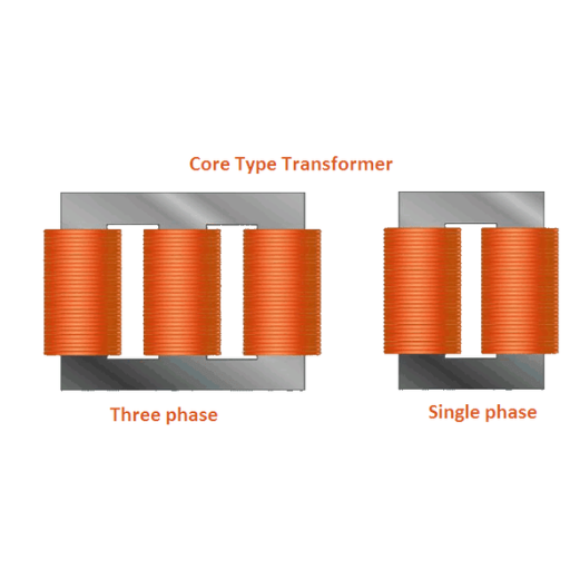
How do single-phase and three-phase transformers compare?

Let’s delve into an important aspect of electrical energy systems – transformers. There exist two fundamentally distinct types of transformers – single-phase and three-phase transformers which vary both in their usage as well as in the magnitude of electrical power that can be handled by them. Single-phase transformers are employed in systems with lower power rating or require single-phase circuits such as in housing developments. These usually employ a single set of windings which makes them relatively cheaper and easier to manufacture. On the other hand, three-phase transformers are commonly intended for commercial and industrial purposes because they work at higher power ratings and can be more effective in the transmission of electric power. These capacitors consist of three windings which are interconnected with each other and correspond to the three phases of power which makes them suitable for large-scale use as they deliver power more efficiently while minimizing energy losses than connecting multiple single-phase transformers in parallel.
Single-phase transformers: Common in residential settings
Because of their efficiency and outstanding performance when it comes to simplicity, single-phase transformers have become a crucial element in residential power distribution. With the use of these transformers, the voltage in single-phase electrical systems which are common in many households is either increased or decreased. It is worth noting that the common primary and secondary winding configuration for these single-phase transformers is cheaper to manufacture and also easy to maintain making it suitable for household use. Such as lighting, heating and use in basic appliances. Although they have less complexity, these transformers provide decent output for voltage levels for a single-phase circuit which in the United States ranges from 120V to 240V. Not to add, the compact design and easy installation of these devices allow them to be used widely and in different areas of the house.
Three-phase transformers: Powering industrial and commercial applications
Three-phase transformers are widely used in industrial and commercial power distribution because they can deal with high power loads. In contrast to the single-phase transformers, three-phase transformers consist of three windings and are interlinked which creates a constant electricity flow without wastage. This provides a balanced load across the supply, enhancing reliability which is crucial for large equipment, factories and big buildings. They can also increase or decrease the electricity voltage across large networks without any disruption throughout various industrial usages in a cost-effective manner.
What are isolation transformers and their applications?

An isolation transformer also known as an ‘electrical isolation transformer’ is a transformer that prevents the direct current (DC) from flowing between two circuits while allowing power transfer between the two. An isolation transformer discreetly provides a high-demand environment with electrical shock reduction as well as ra eduction of the effects of electrical noise and interference. This type of transformer is commonly used in places such as electronics labs, medical equipment, and even industrial factories. Their advantages are the reason why their use is standard as they increase stability in a unit which makes them crucial in such environments.
Safety benefits of isolation transformers
Isolation transformers enhance electrical safety because there is no direct electrical connection between the output and input circuits. The distance also helps to reduce the occurrence of electric shocks since it prevents the occurrence of deep grounding and step potential hazards. They also prevent equipment and the user from faults by surging sensitive equipment from voltage spikes and transients. Besides, they alleviate the dangers of malfunction resulting from magnetic interference by ground loops, which inject dangerous currents into systems. For patient and operator safety isolation transformers are essential in medical environments because they ensure that clean and interference-free power is supplied. This enhancing safety role of these devices is vital in industrial, commercial and health facilities.
Common uses in sensitive electronic equipment
The relocation of electrical systems brings about various issues in the work process along with high productivity levels of sensitive equipment. To tackle this issue Isolation transformers have been implemented. The common usages of these devices can be seen in :
Medical Devices – They are used in hospital equipment such as MRI machines, patient monitors, and surgical instruments to eliminate leakage currents to safeguard patients. Typical technical parameters include input/output voltages of 120V or 230V and reinforced isolation rating of 4 kV or more.
Audio/Video Systems – Audio brands and systems that are mastering devices are expensive, and it is important that they are not interfered with by a ground loop that can lose the signal, this ensures that everything is in good condition. Low Total Harmonic Distortion Transformers are used, as well as step-down transformers.
Data Centers and IT Equipment – used to protect servers, routers and modems against transients and Electromagnetic Interference protection (EMI). The standard parameters are power capacities ranging from 500 VA to 10 kVA for varying load requirements.
Laboratory Equipment – Medical equipment such oscilloscopes and spectrometers require low noise power support. High-frequency Isolation transformers with shielding and attenuation components designed for that purpose are widely used.
Industrial Control Systems – Used in preventing power surges that could disrupt the functioning of PLCs, CNC machines, and other equipment. This type of transformer usually has an overbuilt housing and an isolated secondary winding, which is typically designed for a 480V input.
The incorporation of these transformers improves the reliability and service life of sensitive electronic systems, thereby enhancing their functions in numerous sectors.
References
Frequently Asked Questions (FAQ)
Q: What are the different types of transformers?
A: Understanding the different types of transformers is essential for selecting the right one for a specific application. Transformers come in several types, including power transformers, distribution transformers, instrument transformers such as current transformers, and specialty transformers like dry-type transformers and toroidal core transformers.
Q: What is a dry-type transformer?
A: A dry-type transformer is a transformer that does not use liquid for cooling, instead relying on air circulation or other methods. These transformers are typically used in indoor applications where the risk of oil leakage must be avoided.
Q: How does a current transformer work?
A: A current transformer is a type of instrument transformer used to measure alternating current (AC) by producing a reduced current accurately proportional to the current in its primary circuit, allowing for safe monitoring and metering.
Q: What is the purpose of a toroidal core transformer?
A: A toroidal core transformer is often used for its efficiency and low electromagnetic interference. The toroidal core design offers reduced size and weight and is commonly used in audio equipment and other sensitive electronic devices.
Q: How are transformers categorized based on the number of phases?
A: Transformers are typically categorized based on the number of phases as single-phase or three-phase transformers. Single-phase transformers are used for residential and light commercial applications, while three-phase transformers are used in industrial and high-power applications.
Q: What role do transformers play in power generation?
A: In power generation, transformers are also used to step up the voltage produced by generators for efficient transmission over long distances. This minimizes energy loss in the electrical power distribution network.
Q: Can you explain how a step-up transformer increases the voltage?
A: A step-up transformer increases the voltage by having more turns in the secondary winding than in the primary winding. This allows it to convert lower voltage from power stations into higher voltage for transmission lines.
Q: Why are dry-type transformers preferred for indoor applications?
A: Dry-type transformers are preferred for indoor applications because they eliminate the risk of oil leaks, which can be a hazard in enclosed spaces. They are also known for their low maintenance and environmentally friendly operation.
Q: What are the applications of electrical transformers?
A: Electrical transformers are used in various applications, including power distribution, voltage regulation, impedance matching, and isolation of circuits. They are essential components in ensuring the safe and efficient operation of electrical systems.