


Working with electrical equipment involves knowing how power, voltage and current relate with each other, especially when it looks at the connection and behavior of the transformers. A 225 KVA, which is the standard transformer rating in the industry and commerce, needs to have its amp rating capacity calculated with strict considerations at different voltage levels. This guarantees safe and reliable operation within an electrical system.
In this article, we are going to emphasize explaining important methodologies and calculations that will revolve around Electrical Circuit Theory as applied to the 225 KVA transformer. In particular, the article will explain how to compute for amps given volts, the relation of KVA ratings together with the uses of these transformers in practice. At the end of the article, the reader will have some useful tips on how to use these basic principles in system design and diagnostic processes.
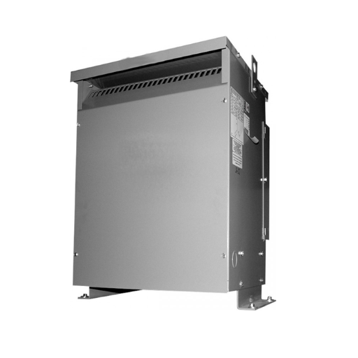
What is a 225 KVA transformer and how does it work?

A 225 KVA transformer is simply an electrical machine that transfers power from one circuit to another through the use of electromagnetic induction. As described by its rating, this device can work with maximum apparent power its measured in kilovolt-amperes (KVA). The most important functional purpose of the transformer is to either increase or decrease the voltage level while keeping the frequency constant, thus allowing the facilitated transmission of power. It works on the basic principle of Faraday’s Law of Electromagnetic Induction where an alternating current in the primary winding produces a magnetic field which in turn induces a voltage in the secondary winding. Thus, the transformer can change voltage levels to the required ones so that different electrical installations can be powered reliably and effectively.
Understanding KVA ratings in Transformers
KVA (kilovolt-amperes) is a non-quantitative way of specifying the apparent power of a transformer, which is a combination of real power (kW) and reactive power. The kVA rating indicates the maximum load that the transformers can withstand without overheating under specific parameters. This metric is important in knowing the efficient current and voltage levels that a transformer can provide to the satisfied content load.
The use of the following formula finds out the KVA rating:
KVA = (Voltage x Current) / 1000
The formula is based on the assumption that the power factor is 1, which is the value that is often stated but does not happen in practice. This rating assists in selecting the right transformer by ensuring that the device in question can meet the power requirements without exhausting the machine hence avoiding tripping. For example, lower kVA ratings are common for switchboard commercial transformers but industrial ones require higher kVA transformers for effective power usage and management.
Across the world standard practice is to label transformers with their kVA rating irrespective of the power factor of the load. This allows for greater generalization of compatibility for different systems and applications including but not limited to utility-scale transformers and distribution transformers. The presumption is that the kVA transformer selected will guarantee several benefits including failures resulting from harmonics or turbulence due to either undersizing or overstressing the transformer.
Applications of 225 KVA transformers in electrical systems
225 KVA transformers are used mostly in commercial power distribution systems, industrial places and institutions. The main role of this transformer is to step up or step down voltage as per the system design so the energy transfer is done without waste. These power large air conditioning systems, machines, or lighting circuits in structures and equipment.
Key Technical Parameters:
Nominal Power: 225 KVA
Primary voltage: The system may present input 480V or 600V.
Secondary voltage: 208V, 240V, or 120/240V( to enable connection with standard loads without violating compatibility requirements.
Operating Frequency: Operates at 60 Hz for systems in North America.
Efficiency: More than 95 % rating is relied upon according to load conditions placed and core design.
Impedance: 3%-6% is generally used to regulate the fault current and enable the system’s performance.
Cooling Type: Dry-type air cools while oil-filled transformers insulate oil for cooling.
They are very effective at regulating voltage and supporting large electrical loads meaning electricity can be supplied to the system and fragile equipment can be supplied continuously throughout operations. They are useful in different voltage ratings and different application requirements.
How do I calculate the amperage output of a 225 KVA transformer?

To determine the output amperage of a 225 KVA transformer, the formula stated here can be applied:
Amperage (A) = (KVA × 1000) ÷ Voltage (V)
When considering a three-phase transformer, the formula given below is used:
Amperage (A) = (KVA × 1000) ÷ (Voltage (V) × √3)
Assume, for instance, that the transformer is fed in three phases with a voltage of 480V, then;
Amperage = 225 × 1000 ÷ 480 √3 ≈ 270.75 A
This computation gives the full load amperes rating of the transformer. Do not forget to check the voltage of the system before applying the formulae.
Taking advantage of the transformer calculator for amp calculations
For ampere calculation with the help of the transformer calculator for example I type the system voltage and the KVA rating of the transformer first. Single phase Constant-Current Drivers use the formula Amperage = KVA × 1000 ÷ Voltage and three-phase Amperage = KVA × 1000 ÷ Voltage × √3. This does away with manual errors since the calculator does the required calculation. This way, I can easily find the full load current and therefore adequately size my conductors as well as prevent damage to my systems, provided I have entered the correct details.
The formula for converting KVA to amps in 3-phase systems
In a three-phase system, to go from KVA to amps, one has to be much more precise as these calculations serve as the basis for designing and protecting electrical systems. The formula used is:
A= (kva x 1000)/( Voltage x 3^)^(1/2)
Where parameters are described as follows.
KVA: A tangible power that the apparatus can provide which is usually specified by the manufacturer.
Voltage: This is the system line-to-line in volts as V. This is the system voltage for operating practices.
Square Root of 3: This is an approximation constant of 1.732 used for the calculations in three-phase power.
Suppose, for instance, the KVA rating of the system is 50 while its operating voltage is 400 V, then the calculation will read as follows.
A= (50 x 1000)/(400 x (1.732)) = 72.3 A
This value indicates the full load current that will go through a whole system when it is at a specific condition. These sorts of calculations are of great importance during the sizing of conductors, performing circuit protection just to make sure that the system will be functional in all of the designated features. Never forget to consider operational tolerances and check necessary standards such as the NEC (National Electrical Code) for standards compliance.
Determining full load amps for 225 KVA transformers
To get the full load amps (FLA) for a 225KVA transformer, one would employ the usual formula for three-phase power systems:
Amperage (A) = KVA × 1000 ÷ Voltage x square root of 3.
As an example, assuming the voltage of a transformer is 480 volts, the A would be:
Amperage =225×1000÷(480×1.732)=270.8A ~270.8A.
This value gives the maximum current that may be supplied to the transformer during full load. It should be noted that FLA is also very important for the circuitry, conductors and for the matching fire and other protection devices by standards such as the NEC. All these factors when combined give a better understanding of the safe working boundaries of a transformer in a defined electrical system environment.
What are the typical voltage configurations for a 225 KVA transformer?
The 225 KVA transformers come in different voltage configurations to meet the needs of the various applications and system requirements. For primary voltage the common options are 480V, 2400V, 4160V, or 13.8kV while for secondary voltages these are often 208Y/120V, 480Y/277V, or 240/120V. The configurations differ concerning the delta or wye transformers. The particular configuration is chosen depending on the class of electrical distribution system, the load to be served and the equipment to be fitted in the upstream and downstream.
Common primary and secondary voltage options
In the case of a supply system transformers are crucial parts and are chosen concerning the primary and secondary voltages and are chosen carefully with optimality in mind to be effective about the system’s needs. Depending on the applications transformers can have voltages like 480V, 2400V, 4160V, and 13.8kV among others which are suitable for industrial settings. On the other end secondary voltage will be based on the load and the output equipment when the power distribution goes through step-down transformers, this secondary voltage is usually rated at 208Y/120V, 480Y/277V and 240/120V. If a transformer has a delta or a wye configuration will also affect the self-balancing of the transformer and the fault-clearing processes. The requirements or regulations as dictated by organizations like ANSI and IEEE have to be complied with to ensure the safety of use. These pairings of voltages are very instrumental in decision-making about power distribution for defined application characteristics.
480V and 208V configurations in 225 KVA transformers
There’s a lot to consider while distinguishing between the use of 480V and 208V configurations of a 225 KVA transformer. Start with some basic facts about the 225 KVA transformer, as both the voltage levels can be utilized depending on how this transformer’s winds are configured, that is whether they are delta or wye and vice versa. For 480V, these transformers find applications in industrial mostly and commercial where they supply heavy machinery or lighting loads. Furthermore, 208V systems are mainly fed from a wye secondary and are deployed in low-voltage distribution systems like residential and light commercial.
The exact configuration choice should depend upon the load, existing infrastructure requirements as well as standards. NEC or ANSI for example. For power distribution systems that require step-down voltages, a 480 V primary and 208 V secondary transformer would be great to use. Neutral grounding is another critical factor, especially for 208V Wye configured systems, considering the safety measures and voltage stability. With these perceptions come significant complexity and design constraints that need to be adhered to, to make sure the systems requirements are met.
Single-phase vs. three-phase 225 KVA transformers
In the case of single-phase and three-phase 225 KVA transformers, the key aspects are their application, efficiency and technical parameters.
Single phase 225 KVA Transformer:
Application: Generally employed in residential or light commercial applications where the load demands are not high and mainly single-phase loads are used.
Voltage Options: Normally set up with the primary voltage of 7200V and secondary of 240/120 V for local distribution.
Efficiency: Not effective for large power demand since more losses result from the use of conversion and additional machinery to serve three-phase supply.
Key Parameters:
Rated Power: 225 KVA
Input/Output Voltage (Examples): 7200V Primary, 240/120V Secondary
Efficiency: About 96-98% depending on the load factor
Impedance Range: Typically 2-4%
Three-phase 225 KVA Transformer:
Application: Mostly used in industries and commercial centers where three-phase engines and distributors operate with higher load targets.
Voltage Options: The most common are 480V delta to 208Y/120V wye for three-phase systems reduction.
Efficiency: Enhanced efficiency and less conductor loss because the load is distributed evenly across three phases.
Key Parameters:
Rated Power: 225 KVA
Input/Output Voltage (Examples): 480V Delta Primary, 208Y/120V Secondary
Efficiency: ~97-99% depending on operating conditions
Impedance Range: Typically 3-5%
Key Differences:
Single-phase transformers are more basic and suitable for central and low-power areas, but the three-phase ones have three times greater load and a much greater efficiency ratio.
Three-phase units remove a large raft of harmonic distortion and produce relatively constant power, unlike single-phase units which are preferable for industrial power applications.
To ensure compatibility between the parameters of a specific transformer and the load, system configuration and placement, as well as norms and regulations, need to be taken into account.
How do I select the right circuit breaker for a 225 KVA transformer?

To set the correct circuit breaker for a 225 KVA transformer, both the maximum working current and the voltage of the transformer’s primary winding must be known. In this particular case, the maximum load current (I) is determined by the formula:
I = 225000 VA / (× 3√Voltage) for three-phase transformers, or I = 225000 VA / Voltage for single-phase transformers.
When full load current is calculated, use a circuit breaker that has a current rating above the so-calculated value. Transformer’s starting e.m.f must also be taken care of to allow the instant inrush current. Also, ensure that the circuit breaker is compliant with other standards such as NEC or IEC applicable in this case, also ensure that the system voltage rating and the fault current rating and coordination with upstream and downstream protective devices have been realized.
Calculating the required breaker capacity
For the determination of the required capacity of the breaker, begin with establishing the full load current as noted previously. For a three-phase transformer, I = (225,000 VA)/(Voltage x 1.732) and for a single-phase transformer use I = 225000 VA/V. With the full load current I defined, the breaker’s size is 125% of the full load current I. This is regardless of the breaker designation as long as the NEC Code is followed.
As an example, let’s say the full load current is found to be 300 A. To accommodate this, a breaker size of 300 A multiplied by 1.25 which gives us 375 A should be adopted thus, a 400 A breaker may be appropriate. This provides that the breaker can withstand inrush currents as well thus inhibiting unwanted tripping of the breaker during transformer start-up. Other requirements such as the rating of the system voltage, the available fault current at the installation point as well as the operations of the over-current devices in the upstream or the downstream direction of the assembly should also be analyzed. The breaker also has to satisfy the requirements set out by the NEC or IEC among others for as breakers are concerned safe and reliable operations are paramount.
Choosing between standard breaker sizes
When I decide on the standard sizes of the breakers I start my work by determining the full-load current of the equipment in question, which is then multiplied by 125 percent. In this manner, I obtain the maximum continuous occurring current and then I opt for the next available breaker standard that is greater than the maximum so that operational in rush currents suffer no undue interruption. If my computation of current gets adjusted to 375 A then I would take the standard breaker of 400 A capacity. Other important information like the voltage of the particular system, the fault current which is most likely to occur at the place of installation, and the coordination with additional protective instruments also come under consideration. A coordinated effort is made towards coordination breakers with each other, as well as compliance with, say NEC or IEC as a means of making sure that there is no compromise on functionality and safety.
Protection devices for 225 KVA transformers
My first step during the safeguarding of the 225 KVA transformer is to find the full-load current of that transformer which is calculated from the rated current and voltage of the transformer. In the case of three-phase transformers, the formula in question is Full-Load Current (A) = (KVA × 1000) ÷ (√3 × Voltage) On the three-phase, at 480 V, we expect full load current to be around 271 A. There is also a reason why I would size the primary protection device as I do: To follow the guidelines of NEC, I can find out the full load current through scaling by 125% approximately. In this case means that around 339 A would be sized, hence normal-sized breakers or fuses of 350 A would suffice. For secondary protection, typically 250% of the secondary full load current at the transformer output side would suffice for compliance with NEC Table 450.3(B) Overcurrent devices would also be important due to short circuit situations and for circuit breakers, current-limiting fuses could be used or in this case, TP.
Effective Coordination with downstream devices is critical to achieve selective fault isolation so that unnecessary tripping does not happen. Also, critical tripping temperatures could be set using temperature sensors or thermostats. Adherence to this standard is critical for any device which is selected to guarantee the reliability and safety of the transformer system as the temperature levels would be comparatively higher than usual.
What are the installation requirements for a 225 KVA transformer?

To accomplish electrical code, safety and compliance, adjustment needs to be made to the installation requirements for a 225 KVA transformer that includes:
Voltage and Current Ratings: Confirm the primary and secondary voltage ratings and ascertain the full-load current to accurately determine the appropriate sizing of the conductors, overcurrent protection devices and equipment related.
Overcurrent Protection: A primary protection that is by NEC table 450.3(B) is to be installed at 125% of the full load current of the transformer for a basic system. Depending on the system design configuration used secondary protection may be proportioned up to 250% of the full secondary load current.
Placement of the Wires: Make the wires considering the full load ampere since the ampacity can be ascertained in NEC article 310 and the ampacity compensates the voltage drop resultant from the distance.
Earth: Make sure that a ground system is made concerning the NEC article 250. Make sure that ground tested, transformer case, neutral and grounding electrode system are linked together,
Air Conditioning: Ensure that there is sufficient clearance and ventilation around the transformer so that it does not overheat, this must be in line with manufacturers’ recommendations,
Position and Access: Ensure that the device is installed in a position that satisfies NEC working area spacing guidelines, that it is not surrounded by flammable substances, and that it is in a serviceable state.
Check-up and Testing: Conduct insulation resistance measurements, ensure that voltages on the primary and secondary windings are both present and also verify whether or not proper grounding has been achieved and the unit is physically sound before applying a voltage to the transformer.
Complying with these requirements maintains safety and effective performance while at the same time remaining within the confines of NEC standards.
Ventilation and cooling considerations
While focusing on ventilation and cooling, I make sure that the transformers are used within their temperature limits by following certain rules. First I check that there are sufficient clearances as specified by the manufacturer to allow circulation of air around the unit. I also check that the location of the installation does not go beyond the transformer’s maximum ambient temperature which many most likely rated at 40 C to prevent overheating. In addition, I provide cooling systems for large transformers when necessary say forced air or liquid cooling systems so that productivity is not compromised during loading conditions. All these measures help improve efficiency and extend the life of the equipment.
Suitable locations and enclosures (e.g., NEMA 3R)
When choosing the proper placement and surroundings for transformer installations, it is essential to consider a vast range of things including the environment, safety, and codes. Transformers should be located in places where they can avoid moisture, dust, and other detrimental phenomena. Locations outside the scope of indoors typically require non-man vents meant for inevitability against conditions like ice rainstorms, these include NEMA 3R.
For construction purposes, all relevant considerations must comply with NEMA standards usually recommended based on the specific areas like NEMA 1 for construction areas with mud or more restrictive NEMA standards if it’s more exposed to interferences and dirt particles. NEMA 4 or 4X enclosures are recommended in cases of washdown environments or chemical exposure due to their resistance to water and corrosion.
A few technical pointers that help in enclosure selection and site location are as follows:
Ambient Temperature Limit: A general rule states a NEMA rating can go extra to a 40°C AT per their placement. Use rating’s warmth guides to choose a location applicable to the guidelines set.
Ingress Protection (IP or NEMA Rating): Ensure and validate the enclosure’s capability to protect from outside hazards. While grossly using it outside, minimum NEMA 3R should be aimed to be used, while those areas affected by corrosives or wet areas even higher NEMA 4X might be needed.
Clearance: Follow the clearance (i.e., usually a distance of 12-36 inches) that is recommended by the manufacturer for transformer ventilation as well as its accessibility and maintenance.
Elevation: Derating the transformer may be necessary at altitudes above 1000 m (3,281 f) and due to air thinning owing to the altitude which lowers the cooling efficiency.
Adhering to these guidelines assures maximum transformer utilization, safety and regulatory compliance (e.g., NEC, IEC) and prolongs the life cycle of the equipment.
Wiring and connection guidelines
Connecting transformers and cabling them requires a lot of attention to certain technical parameters to maintain safety and functional efficiency:
Conductor Sizing: Conductors are chosen based on the transformers’ full load amperes (FLA) rating as well as ampacity and insulation type and temperature rating. It is also necessary to adhere to some standard provisions such as NEC Table 310.15(B)(16) regarding conductor sizing. For instance, a load of 100 A will require at least a minimum of #3 American wire gauge (AWG) copper wire (THHN, rated 75’C).
Terminal Torque Requirements: For all terminations, follow the manufacturer’s recommendations regarding torque values. Overall mechanical stability and overheating will both be ensured. Normal logic would suggest torque values of 20-250 in-lbs depending on the size and type of the connection.
Grounding and Bonding: By NEC article 250, an appropriate grounding system should be established to control overcurrent faults, as well as ensure proper electrical connection. The neutral on the transformer (where applicable) should be connected to an approved grounding electrode. Bonding the enclosure should be done when necessary.
Phase Polarity and Connections: To make sure operations are normal, check that phase sequence and polarity are correct, mainly for three-phase systems. The input and output wiring should agree with the markings on the primary and secondary terminals of the transformer.
Overcurrent Protection: Sized upstream circuit breakers or fuses as required by NEC 450.3 for overload and fault protection of the transformer. For example, the primary protection of a 45 kVA transformer requires a fuse of rating 125% of the full load current.
Voltage Compatibility: Ensure primary voltage input and frequency do not exceed the voltage rating of the transformer and ensure that the secondary voltage is consistent with the load requirements.
With a specific expert’s requirements and parameters, the correct performance of the transformer can be achieved along with the other electrical standards and code requirements. However, it should be noted that such requirements and adjustments are in the respective manufacturer’s documentation so make sure to check it.
References
Frequently Asked Questions (FAQ)
Q: How do I use a transformer calculator to determine the amps for a 225 kva transformer?
A: To calculate the amps for a 225 kva transformer, you can use an amps calculator. For a 3-phase system, the formula is Amps = (kVA × 1000) / (Voltage × √3). For example, if the voltage is 480 volts, the calculation would be Amps = (225 × 1000) / (480 × √3), resulting in approximately 270 amps.
Q: What is the difference between a dry type and an isolation transformer?
A: A dry-type transformer uses air as a cooling medium and is typically used indoors due to its ability to efficiently ventilate heat. An isolation transformer, on the other hand, provides electrical isolation between its primary and secondary windings, which is essential for protecting sensitive equipment from AC power fluctuations.
Q: Can you give a quick overview of a 3-phase 225 kva transformer?
A: A 3-phase 225 kva transformer is designed to efficiently transfer electrical energy in a three-phase power system. It supports high power loads and is commonly used in commercial and industrial settings. It may come with features like a polyester powder coat for protection and an IP14 rating for dust and water resistance.
Q: How do I calculate the required kva for my application?
A: To calculate the required kva, you need to know the total load in watts and the voltage of your system. For a 3-phase system, use the formula kVA = (Watts) / (Voltage × √3). Ensure that the calculated kva meets or exceeds your load requirements to guarantee efficient operation.
Q: What voltage options are available for a 225 kva transformer?
A: Common voltage options for a 225 kva transformer include 208 volts, 400-volt, 480-volt, and 600-volt three-phase configurations. The choice of voltage depends on your specific application and electrical system requirements.
Q: What considerations should I make for installing a dry-type transformer?
A: When installing a dry-type transformer, ensure adequate ventilation to dissipate heat, as they are air-cooled. Check for compliance with CSA standards and confirm that the transformer is suitable for your environment’s temperature and humidity levels.
Q: How can I quickly contact an engineer for support with my transformer?
A: For quick contact with an engineer, check the manufacturer’s website for a quick contact button or customer service number. This will allow you to get up-to-date information and technical support for your transformer inquiries.
Q: What should I do if I need to return any product related to my transformer purchase?
A: If you need to return any product, ensure that it is unused and in stock before ordering. Most companies have a return policy for unused goods returned within a specific period. Check if a guarantee is given unless otherwise stated in the purchase agreement.
Q: Are there any guarantees provided for a 225 kva transformer?
A: Guarantees for a 225 kva transformer vary by manufacturer. Typically, a guarantee is given unless otherwise stated, covering defects and ensuring the product meets specified standards. Always confirm the guarantee terms before purchasing.