


Transformers belong to the class of electrical and electronic apparatuses and perform major roles in power system distribution and signal processing. This blog aims to discuss the classification of transformers, some of their features, and the applications they are designed for. The article intends to start with an explanation of the basic principles of other operations of transformers to set the technical frame. It will then classify transformers based on their intended use, including power transformers, distribution transformers, isolation transformers and other types used in industries and commerce. Also, we will investigate the operating principles and the advantages of the construction features of each type to understand the applications of transformers in big structures and small electronic devices. Hence, readers will understand how transformers are utilized by different industries and how they are located in different power systems.
What are the Main Types of Transformers?

There are several different types of transformers which are divided based on their function, structure and application. The following are some of the main types:
Power Transformers – Installed mostly in transmission networks to raise or lower the voltage levels for long-distance power transfer.
Distribution Transformers – These are transformers that allow the distribution of electricity at usable voltage levels to consumers since they are applied at lower voltage levels.
Isolation Transformers –They are designed to improve safety by providing separation between two or more circuits to reduce the risk of the electrical noise that may cross over.
Autotransformers – They increase efficiency since there are portions of the windings connected to both the input and output thus allowing different levels of voltages to be used.
Instrument Transformers – Used mainly for measurement and protection of measurement and converting systems. They are further subdivided into current transformers (CTs) and potential transformers (PTs).
In conclusion, various types of transformers are useful for different purposes which have made it possible to provide a variety of applications in the industrial, commercial and even residential areas.
Power Transformer Overview
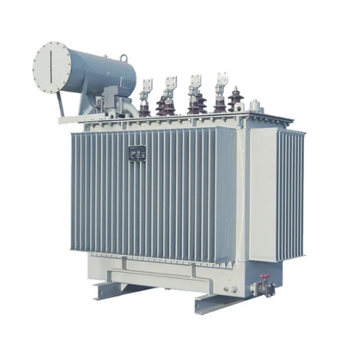
Within electrical transmission and distribution systems, Power transformers are mainly employed in long transmission lines where there is a requirement to pass electric power at high voltages. Thus their main function is to either boost up (step up) or lower (step down) electric voltage with a view of minimizing energy loss on account of resistance through the transmission lines. These devices are usually utilized in substations, power generation stations, and industrial plants and the best efficiency is achieved at full load for these devices.
Power transformers are built using materials that are expected to withstand high temperatures and electrical stress. Core construction is extremely important. The core is constructed using low-loss silicon steel laminations to increase magnetic efficiency. In the same fashion, however, oil or air-cooling systems are employed in the construction of power transformers to ensure proper working temperatures during use.
Of utmost importance is power transformer reliability and efficiency, as they influence the stability of the electrical network. There have been numerous advances in power transformer technology. Newer devices are incorporated into power transformers, which use automation and smart monitoring concerning power consumption, and several parameters predicting the time to perform maintenance and to avoid expensive breakdowns. Their integration makes it possible to provide a reliable flow of electric energy through interconnected networks around the planet.
Distribution Transformer Explained
A distribution transformer can be said to be a type of transformer that is used to step down the higher transmission voltage to a distribution voltage suitable for residential, commercial, or industrial users. These transformers serve the consumers of electricity continuously, providing the required voltage at the load with the least drop in voltage while ensuring high efficiency. They are usually lower power rated and located very close to the load center. Amorphous core technology and some ingenious design changes have improved their energy performance and operational reliability. New technology has evolved and smart distribution transformers are supplied with monitoring systems for performance control, predictive maintenance, and control of energy losses.
Understanding Instrument Transformers
Transformer instruments are used in electrical engineering to scale down a very high voltage or current into a smaller standard value that can be measured by measuring instruments and protective relays. They usually come in two types saw- current transformers (CTs) that measure current, and potential transformers (PTs) that measure voltage. Both these types make it possible to monitor important electrical parameters while ensuring safety from high voltage by using isolators in the measurement equipment. They can measure certain parameters of an electric circuit without being connected directly to the power source. Recent times have seen developments like the digital output modems and the smart grid connection which increases accuracy through real-time data integration.
How Do Transformers Work?

Transformers work through electromagnetic induction, allowing the transmission of electrical energy from one circuit to another. They comprise two or more coils twisted around a magnetic center. Alternating Current (AC) in the first coil produces an electromagnetic flux in the center which induces an electromotive force in the secondary coil. Transformers are designed to either increase or decrease voltage depending on the ratio of turns in the primary and secondary coils. This makes transformers particularly important for the effective transmission and distribution of electrical energy over long distances.
Role of Primary and Secondary Winding
A transformer has primary and secondary windings which aid in the conversion of electrical energy by electromagnetic induction. The primary winding, which is linked to the power supply, creates an electromagnetic field when a current flows through it. This flux integrates with the magnetic core and generates a voltage in the secondary winding by mutual induction. The transformed output voltage is then sent to the load through the secondary winding. The ratio of the number of turns of the primary and the secondary windings determines the transformation ratio which either increases or decreases the voltage depending on the usage of the transformer. The clearer or more simple the functional relationship is, the better the energy conductivity will be with lesser possible loss of energy.
Importance of Transformer Core
The transformer would not function efficiently without a core. Its main purpose is to allow for low reluctance between the lines resulting from the magnetic flux and ensure the primary and secondary windings are efficiently coupled. The core minimizes hysteresis energy losses and eddy current losses thus increasing the operating efficiency of the transformer. Likewise, the core’s composition and making, such as lamellated silicon steel, are intended to produce good performance with minimum heating effects. If the core was designed poorly, the transformer would not be able to operate effectively, which would increase power losses and lower reliability in electrical systems connected to it.
Function of High Voltage in Transformers
High voltage is the most critical phenomenon in the operation of transformers since it allows for the minimization of the amount of current transferred through the transmission lines hence greatly reducing resistive losses which are equally proportional to the current. In expanded power systems, the energy efficiency achieved increases the reliability of the whole system and decreases the operational costs of the power network.
Everything is based on a fundamental equation that states that the power is equal to the product of voltage and current that is P = V × I. If the same amount of power must be delivered at a lower current, this means that the voltage must be increased using a step-up transformer. For example, when a transformer is used to supply voltages in the range of 110 kV to 765 kV, this step reduces the amount of current supplied to the power lines thereby reducing resistive losses and also reducing the strength of the structures supporting the cables.
Moreover, with the increased levels of electrical stress in high-voltage transformers, the selection of materials and the design of insulation must also change. Insulation materials must also be tested under parameters of breakdown voltage a few hundred volts above the working voltage. If the application rate of any insulating materials or even a complete insulating layer cannot withstand high breakdown voltages, it would develop problems within kilovolts.
Transformers enhance the reliability and efficiency of a system, guaranteeing that power execution to the users is optimized by increasing and subsequently decreasing the voltage at the distribution level.
What are the Different Types of Transformers Based on Core?
Transformers are two types of transformers distinguished according to the type of construction of the core.
Core-Type Transformers
A core-type transformer utilizes a core with a substantially rectangular shape and in two of its opposing limbs windings are wound. This class type is more used in high voltage applications because of its efficient cooling performance and allows for easy maintenance of windings as well.
Shell-Type Transformers
Shell-type transformers have windings enclosed with a core umbilicus that aids in resistance strengthening and reduction of leakage flux. Hence this type of transformer is well suited for low voltage, high current applications where small size and strong structure are needed.
Both designs aim at specific operational requirements and are picked out according to application requirements, voltage, physical constraints, etc.
Iron Core Transformer Features
To improve efficiency and decrease energy loss, iron core transformers make use of a laminated iron core. This design considerably lowers the eddy current loss caused by the lamination of the core which limits the flow of induced currents. These transformers are known to be quite efficient in transferring energy from one circuit to another through the use of electromagnetic induction. The use of iron core transformers is common in high power applications since the iron material has superior magnetic properties thus allowing a higher flux density than other core materials. Furthermore, their solid construction promises dependability and durability across multiple working environments making them ideal for use in both industrial and utility-grade power systems.
Air-Core Transformer Characteristics
Fundamentally, what distinguishes iron-core transformers from air-core transformers is the class of materials used as the core medium, as the latter employs air and other such non-magnetic materials. This design bypasses the issue of core losses completely and renders a better efficiency provided there are no hysteresis or eddy current effects. Because of their low energy loss during high-frequency operations, these transformers are useful in radio transmission and signal processing where high-frequency applications are needed. Air-core transformers tend to have low inductance as a result of not having a magnetic core however, they also require more turns of wire to achieve the desired performance.
Technical Parameters:
Operating Frequency Range: More than 1 MHz.
Inductance: It is dependent on the amount of winding and the geometry, but always less than iron core transformers.
Power Capacity: Limited to low-power applications owing to low magnetic coupling efficacy.
Efficiency: In high frequency applications with less load, efficiency is about 95% and above.
The architecture guarantees superior performance for specific applications which require low distortion and high-frequency operations.
Ferrite Core Transformer Advantages
High-Frequency Performance: Ferrite cores are well known for their increased application at high frequencies, typically greater than 1 MHz and this is crucial to keep core losses to the minimum.
Low Core Loss: Since ferrite material is non-conductive, eddy current losses are minimized, thus improving system efficiency – usually more than 95%, particularly in low-power, high-frequency applications.
Compact Design: The utilization of ferrite increases the magnetic permeability enabling the construction of smaller transformers which require less winding and are best suited for confined spaces.
Thermal Stability: The ferrite materials exhibit good thermal characteristics since they can work effortlessly over extensive temperature ranges without any drastic changes in their properties thereby facilitating reliable operation in harsh conditions.
Low Leakage Inductance: The ferrite core’s shape and properties serve to reduce leakage inductance which enhances the energy transfer efficiency within the transformer.
These characteristics guarantee that ferrite core transformers are suitable for use in high-frequency regimes for switching power supplies, RF circuits and inductor-based systems.
How Do Winding Configurations Affect Transformer Performance?

Taking into consideration the performance characteristics of a transformer, the winding configurations are of significant importance. The positioning of the primary and secondary windings affects the voltage transformation ratio, efficiency, and even EMI. As an example, if the configuration of the windings is maximally resisted loss and fully coupled between the windings the efficiency is maximized. Moreover, interleaved ones have a low leakage inductance which is also very important in high frequency applications. The winding geometry such as layered, bifilar and helical is selected depending on the voltage, current and frequency which will guarantee good quality and efficient utilization of the transformer in various applications.
Single-Phase vs. Three-Phase Transformer
Transformers are electrical devices that use electromagnetic induction to transfer electrical energy between circuits. There are two types of transformers — single-phase and three-phase. Single-phase transformers are extensively used for low-power applications while three-phase transformers cater to the needs of high-powered patrons. Single-phase and three-phase transformers have a varying number of circuits, leading to a difference in their weight, design, and wattage rating.
A single-phase transformer includes a primary and a secondary winding. The electrical energy in the system is transferred through electromagnetic induction. Applications such as small residential setups and commercial areas where the load is relatively small utilize single-phase transformers for lighting or heating. One constraint with using a single-phase transformer system is the inability to transfer power over long distances as efficiently as with three-phase systems.
Alternately, a three-phase transformer has a higher power rating and is used for commercial power supply of large buildings and chains of factories. The three-phase setup uses three windings offset from one another for increased efficiency. Positive and negative wires are used to provide a constant electric flow over time. While a three-phase transformer is more complicated and pricier, the fact that it delivers greater reserves in energy systems and higher efficiency over transmission makes it a widely used solution in power utilities.
The target power rating, load scalability and overall application complexity assist the user in determining whether a single-phase or a three-phase transformer would work best. both transformers are essential when it comes to modern electrical systems and load-balancing efforts.
Toroidal Core Transformer Benefits
Toroidal core transformers have several important benefits which makes them very popular in many applications. Firstly, owing to their configuration, they suffer a tremendous reduction in the level of EMI and hence operate relatively noiseless, which is a prerequisite in delicate electronic equipment. Secondly, they are very economical since they have low core losses and invariably achieve an efficiency rate of the order of 95%, and hence lower energy usage. Furthermore, the size and weight of toroidal transformers are less than that of conventional laminated core transformers, which allows great convenience in design and installation. Their design also contributes to more efficient cooling of the device, hence better reliability and durability. These advantages make them particularly suitable for various audio devices, medical equipment, and other systems with increased requirements for accuracy and efficiency.
What are Specialty Transformers and Their Uses?

Specialty transformers are custom-designed electric transformers which are suitable for particular applications. They are different from conventional transformers since they are developed to satisfy electrical requirements or environmental conditions that are unique. Specialty transformers include isolation transformers, autotransformers and high-frequency transformers. Their applications cover a diverse range of sectors – medical transformers guarantee patient safety in healthcare devices, control transformers guarantee accurate voltage levels in industrial machines and high-frequency transformers are required in communication devices and electrical power devices. It can be said that these transformers are indispensable in meeting the performance, reliability and safety requirements of specialized applications.
Exploring the Isolation Transformer
An isolation transformer prevents there being an electric connection between two circuits but allows the transfer of power. The isolation transformer has one main aim which is to reduce electrical noise and improve safety by separating the Primary junction from the secondary. In turn, this separation guarantees that faults or surges in this instance do not pass directly to the other side from one side preventing the users as well as the equipment from being affected.
Key Features and Applications
Electrical Isolation: Isolation transformers electrically separate the input and output connections eliminating a direct electrical connection this is very important in cases where electrical shock could be an issue.
Noise Reduction: These transformers also lower the common mode noise or electromagnetic interference which enables delicate parts to function smoothly and perfectly. They are therefore important in medical equipment, laboratory instruments as well as sound engineering equipment.
Voltage Transformation: They can also increase or decrease voltages according to the application needed while ensuring separation and insulation.
Safety Standards Compliance: Various isolation transformers comply with UL or EN regulations which suit them for use in critical places where safety and operational dependability is a must.
Standard Technical Specifications
Voltage Classifications: The transformer’s input and output voltage levels are application-specific. Most designs such as the medical grade transformer types usually operate at 230V or 110V.
Power Rating: Predominates anywhere between 50 VA to 5,000 VA and above the ranges which depend on the load requirements
Insulation: It is rated to exceed 1 MΩ in most cases which is viewed as efficacy and assurance of the transformer safety.
Dielectric Rating: Isolation ratings of the transformers range between 1,500-5,000 V AC depending on the level of electrical isolation required
Frequency: General models of isolating transformers operate at 50Hz or 60Hz, other types for high-frequency applications can operate at several kHz.
Examples of Isolation Transformer Applications
Medical Sector: Protection from leakage or surge currents to the patients and highly sensitive devices in the exercise of voltage isolation during surgical operations and in other diagnostic machines
Industrial Machinery: Maintains moderate voltage levels and offers protection to systems embedded with motor drives and CNC machines
Consumer Electronics: Provide better noise suppression on amplifier devices to prevent interaction with other devices while the equipment is in operation.
Isolation transformers can offer protection and at the same time allow on to integrate elements into the design making them essential components in a range of appliances and systems in industrial, medical and commercial centers.
The Role of the Step-Up Transformer
In my opinion, the most important function of a step-up transformer is to transform a voltage from a lower to a higher level, preserving the power that is delivered at the input and the power that comes out of it, except for some minor energy losses. This is important for instance in power transmission where higher voltage means lowering the current and so less energy loss over long distances. Also, step-up transformers are applied in some distinct systems such as renewable energy grids, where more specifically solar inverters and wind turbines operate to match the electricity produced to grid voltage levels. Their effectiveness and stability make them an indispensable element in the contemporary power system.
Understanding Voltage Transformers
As I see it, voltage transformers are meant for the transformation of electrical circuits in different applications either by stepping up or down the voltage. To transfer power efficiently over long distances power supply systems employ step-up transformers to increase the voltage which in turn decreases the current and reduces energy losses on the transmission medium. On the other hand, household and industrial needs are catered by step-down transformers which reduce the voltage to a safer range. Their operation is centered on the application of electromagnetic induction laws to effect the transfer of power between the electrical circuits while maintaining electrical isolation between the circuits. These devices are crucial to maintaining the desired level of energy output, safeguarding expensive instruments, and avoiding malfunctioning of different electrical systems.
References
Frequently Asked Questions (FAQ)
Q: What is a transformer?
A: A transformer is a device used in power distribution systems to transfer electrical energy between two or more circuits through electromagnetic induction. It changes the voltage levels to facilitate power transmission and distribution.
Q: What are the different types of transformers?
A: There are several types of electrical transformers, including step-down transformers, single-phase transformers, three-phase transformers, dry-type transformers, air core transformers, and current transformers. Each type is used for specific applications in power systems.
Q: How does a step-down transformer work?
A: A step-down transformer reduces the voltage from a higher level to a lower level. It has more turns in the primary winding than in the secondary winding, resulting in a lower output voltage. This type of transformer is often used in power distribution to make electricity safe for use in homes and businesses.
Q: What is the purpose of a single-phase transformer?
A: A single-phase transformer is used in power distribution systems for applications that require a single-phase supply. It is commonly used in residential and light commercial settings to provide a consistent voltage level for electrical devices.
Q: What is the role of the primary winding in a transformer?
A: The primary winding in a transformer receives the input voltage and creates a magnetic field. This magnetic field induces a voltage in the secondary winding, allowing for the transfer of electrical energy between circuits. The winding ratio between the primary and secondary windings determines the voltage transformation.
Q: What is a dry-type transformer?
A: A dry-type transformer uses air instead of liquid for cooling its coils. It is typically used in indoor applications where environmental conditions require a reduced risk of fire hazards. These transformers are widely used in commercial and industrial settings.
Q: How does an air-core transformer differ from other types?
A: An air core transformer uses air as the core material instead of iron or other ferromagnetic materials. This type of transformer is often used in applications requiring high-frequency operations, such as radio frequency (RF) transformers, where minimizing core losses is critical.
Q: Why are current transformers used in power systems?
A: Current transformers are used to measure high current levels in power systems by reducing the current to a manageable level for measurement instruments. They are essential for monitoring and controlling electrical systems and are typically used in conjunction with protective relays.
Q: What determines the winding ratio in a transformer?
A: The winding ratio in a transformer is determined by the number of turns in the primary winding compared to the number of turns in the secondary winding. This ratio dictates the voltage transformation between the input and output circuits, allowing for either step-up or step-down voltage conversion.