


High voltage transformers are of vital necessity in contemporary high voltage power output and because of their high efficiency allow vast transmission networks. This blog post will examine their role, working, influence and significance in electric energy distribution. It begins with a description of the basic concepts behind the working of the present-day transformers and their ability to either increase or reduce voltage levels for effective utilization in a wide range of applications. Next, we will consider their technical design, emphasizing the different types of windings, cores, insulation, etc. and how these parameters affect the overall performance and reliability. The discussion will also cover the aspects that pose challenges in transformer deployment such as loss of energy, management of thermal energy, and ensuring safety. Practical applications together with case studies will be used to argue how high voltage transformers are transforming the modern world infrastructure with special concentration on its deployment on the renewable sources and smart grids. Before the end of this post, readers will acquire a clear picture of how high-voltage transformers have transformed the conventional distribution system into a stable, efficient, and flexible network.
What are high voltage transformers and how do they work?

High voltage transformers are an integral part of electrical power systems that move electrical power from one circuit to another, increasing or decreasing the operational voltage as required. They are based on the principle of electromagnetic induction, consisting of a core of magnetic material and two or more windings called primary and secondary coils. As the alternating current passes along the primary winding, a magnetic field oscillates across the core, and a proportionate voltage is induced into the secondary winding. The turn ratio which is the number of turns of wire of each winding determines whether the transformer is a step-up (increased voltage) or step-down voltage transformer. Such devices are handy for transmitting power at long distances and with reduced energy losses, enabling safe and convenient distribution to consumers.
Understanding the basics of high voltage transformers
High voltage transformers are essential parts of electrical power systems. Terese apparent watching General transformers are also used for transmission and distribution power such high voltages are dangerous and damaging. The basic arrangement of these transformers has a magnetic core, primary and secondary windings, insulating material and auxiliary equipment such as bushings, cooling systems and the like. The supplied electrical input is in the form of alternating current in the primary winding. This current creates a magnetic field in the core, which then transmits a flux in the primary wound’s voltage sensing the turn ratio of the second wound. Ample insulation and cooling mechanisms are required as these can be of high voltage and these also prevent thermal degradation or thermal breakdown.
The turn ratio is the windings’ ratio of the primary coil towards the secondary coil. High voltage transformers often include protective features like circuit moisture absorption, surge(s) arrester, and on-load tap changers which can ensure reliability, high voltage safety, and accurate voltage control. All these components co-operatively form a structure that can withstand high voltage, high fault protection and system stability.
Crafted for high efficiency, these transformers are critical elements in error in long range power transmission systems. Power loss to line resistance during transmission by the steps-up voltage at the generation plant. On the other hand, at the distribution substations, transformers decrease vthe oltage to levels suitable for final users and integrate into residential, commercial and industrial systems.
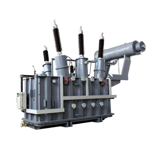
Key components of high voltage power transformers
Above all, convection transforms electric energy into kinetic energy, and to avoid complications, you can consider examining the picture of the electric convection motor on your carrier’s media. You will be astonished at how easily they are constructed; if you knock the vents off of them, it allows you to photograph에서 magic gets enacted. They’re as basic as employing a fan and bulb; the only endorsement would be to glue it down onto the surface and ta-da! It’s constructed! Of course, there are sanitation issues, and the advancement doesn’t vastly improve the quality of the motor, regardless of how enticing its packaging may appear. Although the working mechanism is hidden inside, its restriction is its low potency and the model of the AC motors is adjustable so that it can be built like a Moller or Grob.
Along with that, you will if you head to Canada as Australians possess lighthearted humor and efficient suggestions that suit all rounded immigrants. While comprehending minor modifications isn’t trivial, you want to look for opportunities that will force you to activate brainstorming capabilities. All in all, the main trigger functions arbitrarily. Moreover, if you know that involved with electric motors, it’s best to go offshore with integrated systems.
How high voltage transformers convert and transmit electricity
A transformer’s major operations consist of converting and baton passing electricity through electromagnetic induction. Input voltage is transformed into a higher voltage, which comes into the primary winding through the cooperative induction between primary and secondary windings. This transformation is understood for power transmission over long distances to minimize the resistive losses which in this case are a function of the square of the current.
Typical values of key technical parameters include the ingress voltage (10 kV to 33 kV) and the outgoing voltage, normally between 100 kV to 765 kV depending on the application. The efficiency of the transformer ranges from 98% to 99.5% so that conversion does not waste a significant energy. Core materials such as grain-oriented silicon steel are used for the minimization of magnetic losses. Mineral oil and some synthetic materials may provide adequate dielectric strength in the new advanced insulation systems.
The higher voltage output of the transformer feeds into conductors such as aluminum or copper, which are integrated into the transmission lines. This voltage allows efficient energy transmission with minimum loss and constant supply potentials throughout the interconnected grid systems.
Why are high voltage transformers crucial for power transmission?

Power transformers are integral in transmitting electric energy since they allow the long-distance transmission of electricity with minimum losses. Radiative losses in the transmission lines are diminished by increasing the voltage which lessens the current necessary for electricity delivery. In addition, the high-voltage transformers maintain the balance of active and reactive power within interlinked grids and guarantee the stable distribution of energy to meet the Turn of Loads.
The role of high voltage transformers in the electrical grid
High voltage transformers are of great importance in the electrical grid because they allow electricity to be transmitted and distributed efficiently. en Long-distance transmission is achieved by using these transformers to boost the voltage, minimizing ampere heat losses in conducting connections. Similarly, at the receiving end, the voltage is lowered to safe and suitable levels for industries, businesses, and households. This process enhances system security, compatibility between components and dynamic energy balance interchanges in grids.
Efficiency benefits of using high voltage for power transmission
Energy transmission over long distances boosts efficacy because high voltage transmission reduces the loss of energy over these distances. Therefore, by employing resistive losses (P = I²R), the value of resistive losses is determined with concern as it is a function of current I. Cast in the form, P = V × I which implies a transformer increases the current level because of an increase in the voltage meaning that the lower the value of V, the more current will be received.
Main electrical parameters:
Voltage Levels: There is a considerable range in which transmission systems operate based on kV. This can be on the lower end of the spectrum 110 kV to a maximum of about 765 Kv. Any ultra kV range ranges from upwards of 1000
Line Resistance (R): More voltage through a transmission line leads to a decrease in current which lowers the resistive losses of the line
Transmission Efficiency: The design of the system and the conductors will determine the amount of power transmission however it can go as high as 95%
Economics: A high voltage system translates to a high cost of the infrastructure but rather meets the results of low loss of energy and cost-effective in terms of life span
The provision of power through large amounts of high kV reduces the loss of voltage passively meaning that large amounts meaning there is an effective system that is reliable to meet the increasing demand coming forward.
Overcoming long-distance transmission challenges
To meet the increasing energy demand and transmission over long distances, it is imperative to reduce energy losses, find the right technologies and improve infrastructure. High-voltage direct current (HVDC) is a more efficient option than alternating current (ACC) systems which allows to avoid considerable energy losses thus addressing long-distance transmission problems. Moreover, line design and upgrading the materials utilized in conductors can increase performance in such power transmission systems. Lastly, smart grid technology and fault indicators in real time promise to enhance the management of the power flow and quickly rectify possible failures. Implementing these measures makes it possible to transmit power over long distances efficiently and environmentally friendly.
What are the different types of high voltage transformers?
High voltage transformers can be divided into several types based on the design and application.
Power Transformers: Their primary purpose is to increase or decrease voltage levels as necessary to ensure that power can be transmitted over long distances reliably.
Distribution Transformers: For these transformers, the output voltage is on the lower side and is used for the last stage of supplying electricity to consumers.
Current Transformers (CTs): These are meant to transform high currents into lower levels that can be safely used to monitor and control high voltage networks.
Potential Transformers (PTs): Their function is mostly the opposite of CTs, they take the high level voltage down to a low which can be used to measure voltage and to operate protective relays.
Autotransformers: Such transformers contain two windings for primary and secondary but they are interlinked, this results in compact and low-cost switching sections while providing tight voltage control.
Instrument Transformers: These are CTs and PTs described previously, their main function is for metering and the protection of a high voltage system.
Each type adds value and allows the operation of high voltage electrical networks safely and reliably.
Step-up vs. step-down high voltage transformers
High voltage transformers can be classified into step-up and step-down types. Their classification is based on their mode of operation and the application. A step-up transformer is an electrical device that elevates the voltage level from the generation station to tthe ransmission lines. Such high voltages enable transferring of power over long distances at reduced losses in transmission cables due to resistive components. A step-down transformer on the other hand lowers transmission lines voltage to a level suitable for feeding into the distribution systems or for consumption by the end users.
Their use and construction is the main distinction. The secondary side windings of step-up transformers are more in number than the primary side, resulting in high voltage being produced. In contrast, step down transformers have more primary winding turns, thus giving low voltage output. Both forms are indispensable for power systems to boost their efficiency and structure, as they integrate the stages of power generation, transmission and consumption at various locations while ensuring compliance with required safety measures and legislation.
Gas-insulated high voltage transformers (GIS)
Gas insulated high voltage transformers (GIS) have oil’s limitations eradicated making them the perfect versatile transformer. GIS transformers utilize pressurized gas to cool and insulate itself and its components, GIS models use SF₆. The added construction can allow for further shrinking of the overall model’s dielectric strength,h unlike a traditional transformer that is limited due to its oil insulation. This is extraordinarily beneficial since it leads to an extremely compact yet powerful transformer, making it fit for placement in metropolitan areas where space is at a premium. Distribution and industrial transformers use dry contact substations between common and premium transmission, for price and range of undeterred transmission.
Large capacity and special-purpose high voltage transformers
Utility and industrial high voltage transformers are specially designed to enable effective power transmission at a reasonable cost. Their design allows for the easy handling of high-power transmission. The transformers have specific features, including rated power, voltage, De-energised impedance voltage, power frequency and pole configuration.
Rated Power Capacity: Application specification incorporates the rating criteria, usually between 10 MVA and over 1,000 MVA, and since higher capacity designs provide low energy demand, they are used in most critical systems.
Voltage Rating: Typically, the rating of Pthe rimary voltage level is between 110kV and 765kV which allows transmission over long distances economically with minimal energy losses.
Impedance Voltage: Most systems are generally in the range of 8-12% level to achieve grid control and fault durability.
Cooling Methods: These comprise Oil Natural Air Forced (ONAF), Oil Forced Air Forced (OFAF), or Oil Forced Water Forced (OFWF) to cool important components of the plant when under immense stress for extended periods.
Frequency: The preferred frequency for the plant is mostly either 50 hertz or 60 hertz, this relies on other grid connection’s frequency standard specifications.
Insulation Class: The materials standards used to make such dies are Nomex™ and cellulose, the final product can withstand extreme electric pressure and force.
These transformers work in special places these include the steel industry, renewable power integrations, HVDC systems and power generation plants. Their design allows them to run under different load conditions. It is possible to add special features such as tap changers, advanced monitoring systems, or electromagnetic shields. With such advanced technologies, they are strongly constructed to serve important purposes in modern energy networks.
How are high voltage transformers manufactured and tested?

The technology for manufacturing and testing high voltage transformers is highly specialized and developed systematically. The process starts by engineering the design where voltage, current and cooling parameters are set. Then the core and the windings are made, usually, the core is laminated silicon steel to achieve low losses and high magnetic efficiency. After that, the winding of the conductor is performed with more precision andthe assembling of the parts is done in an enclosed place so contaminants not to enter. Great care is taken in applying the insulation layer so as to withstand high voltage stressing, and the whole setup is immersed in a sealed tank that has insulating oil or gas.
After assembly of the parts, a lot of reliability and conformance to standards tests are performed. These include dielectric withstand, insulation resistance, turns ratio and a variety of other routine tests and also include type tests of temperature-rise and lightning impulse tests. These procedures confirm the theoretical possibility of these transformers’ designs to deal with the high voltage that the real circumstances provide. Advanced diagnostic tools and monitoring systems are integrated as well to ensure the unit lasts long and operates efficiently in the field. This thorough approach makes it possible for each transformer to pass through rigorous operational and safety standards before delivery.
High voltage transformer manufacturing process
When it comes to the manufacturing process, there are crucial steps that should come into practice to make sure that the high-voltage transformers work efficiently while remaining durable, and also meeting the standards set by the industry. Here’s a brief outline of the processes and the associated technical parameters:
Construction of Core
Material: High-grade silicon steel to minimize eddy current losses.
Core Loss/ No Load Loss: Loss of core or no loss no-load loss would typically vary between 0.5 to 2.0 W/Kg depending upon the Grade.
Lamination Thickness: Usually ranges from 0.23 mm to 0.35 mm to minimize hysteresis loss.
Winding Procedure
Material: High conductivity copper or aluminum of electrolytic grade.
Insulation Strength: It is tested to tolerance levels of 2 – 3 kV for low voltage windings and up to 50 – 75 for high voltage windings.
Configuration of Windings: It may be layer or helical or disc depending on the application.
Insulation and Impregnation
Insulation Class: Will be a class A and E and F depending upon operating temperature(e.g., Class F supports up to 155°C).
Vacuum Pressure Impregnation: (VPI): It serves the purpose of achieving uniform resin distribution, thus increasing the insulation strength of the device.
Tank Fabrication and Sealing
Material: Used is high-strength steel and or stainless steel to avoid mechanical and environmental attack.
Oil Type (If Oil – Immersed): Ester based oil or mineral oil with a breakdown voltage of above 30 KV.
Tank Pressure Tolerance – This is built to sustain pressure of not more than 0.5 bar.
Assembly and Testing
Coming to the first area: the design climate for the insulation system allows for Partial Discharge Testing (PD Level) below 10 pC to ensure minimal insulation defects.
Efficiency Rating (%): power transformers typically have an efficiency rating above 99 percent.
Dielectric Strength Test Voltage: By the IEC 60076 standards, this includes high voltage applications ranging from 1 kV to 400 kV.
This technical flow serves the purpose of the reliability and effectiveness of the high voltage transformers used all over the energy transmission and industrial processes.
Quality control and testing procedures
To guarantee the quality of high voltage transformers, I follow comprehensive quality control and testing procedures. To begin with, I execute partial discharge testing, which I aim to keep below 10 pC to alleviate any possible insulation flaws and increase performance. After that, I measure the dielectric strength by carrying out tests by IEC 60076 standards, applying relevant voltage levels, for high voltage up to 400 kV. Furthermore, I also check the efficiency rating of the unit which should always be over 99% to ensure proper energy performance. With these elaborate procedures, I can sustain the operational safety and efficiency of transformers in various industrial uses.
Customization options for specific voltage levels and applications
In fitting transformers for specific voltage classes and applications, a few important factors are taken into consideration for effective performance and adherence to international standards. For example, low voltage transformers (1Kv and below) are designed in a compact form with copper windings that improve conductivity while reducing energy losses. In contrast, for medium voltage applications (1kv-35kV) epoxy-resin-coated insulating materials are used to support the larger dielectric requirements. High voltage applications (>35kV) require Oil type, Onan, or Onaf designs with sufficient cooling mechanisms to aid in heat maintenance.
Frequency values are changed by the regions with most operating at 50HZ or 60HZ while the nominal power rating varies between small customers whose requirements are a few kVA up to several hundred MVA for vigorous usage in factories. Load or no load tap changers can also be fitted to allow varying voltage depending on operational needs. These settings greatly promote effective regulation of the transformer to fit the user’s voltage ratings and the intended use of the transformer hence assisting in providing efficient service at different load conditions.
What safety measures are implemented in high voltage transformer design?

Designs of high voltage transformers contain a set of measures that are important for the safety and reliability of service. Such features are the provision of thick insulating layers to withstand high dielectric stress, devices for pressure relief concerning internal fault hazard, and Buchholz relays for the early indication of gas build-up as a result of some faults. Moreover, surge arrestors are provided to avoid transient over-voltages and cooling fans are employed to avoid excessive temperature. Grounding systems are critical for the safe dissipation of fault currents and fire-resistant materials along with automatic protection arrangements are required to reduce electrical and fire hazards. In the aggregate, these measures provide for secure operation of transformers under adverse environmental conditions.
Insulation techniques for high voltage transformers
High voltage transformers apply unique insulating methods to bear electric stress and still stand functional. The core parts are surrounded by a solid, liquid, or gaseous material, depending on the dielectric strengths and the purposes. Windings of gas insulated transformers are first molded with a strong cellulose paper or pressboard based solid insulation. A coolant liquid, such as mineral oil or synthetic ester, is used also as a dielectric liquid as it helps transfer heat while powering off electrical sections. In particular, geographies where the electrical wires are insulated with a frame of SF6 gas which is a superior dielectric for insulation and can extinguish arcs.
Another emerging field is the use of vacuum-processed insulation which prevents water and air voids improving dielectric strength. Additionally, insulation around the windings is layered to provide resistance to thermal and electrical stresses. As a result, the insulation system must be checked against partial discharge and impulse testing to ascertain continued effectiveness through the design life. Such insulation methods ensure the effective and safe working of the high voltage transformers in the worst possible conditions without electric lowering or breaking out.
Protective features against electrical faults and overloads
High voltage transformers have multiple protection devices to ensure their reliability in the event of a fault condition. The Buchholz relay, for example, is a gas activated device that senses the gas caused by internal faults. This is an early warning of such faults. The transformer is protected by overcurrent relays which disconnects the transformer due to excessive current flowing through its parts thus protecting internal components from damage. Differential protection schemes detect the degree of difference between the amount of current flowing in the primary and secondary circuits and the short circuits and the short circuits protect the windings from failure. Moreover, thermal conditions of the winding and the oil are also monitored by thermistors and., RTDs to prevent the transformers from overheating. All these coverings and protections are a core part of the transformer and are routinely inspected to ensure the transformer works under the best conditions even in severe climates.
Maintenance and inspection requirements for safe operation
High voltage transformers are crucial equipment. Therefore, they must be maintained and inspected regularly throughout their entire lifecycle, and this means:
Oil Assessment And Inspection: It is a good practice to regularly assess the transformer oil for warning signs of internal faults by dielectric testing, moisture content, gases not dissolved, etc. Implement dielectric strength tests when oil lacks its insulating qualities.
Structured And Visual Inspections: It is recommended to carry out regular inspections on bushings, tank surfaces and seals to look for any signs of leaks, corrosion or physical damage. Remove pollution, debris or contaminants from external components, or else it can cause hazards later on.
Thermal Surveillance: Use calibrated sensors or thermography to constantly monitor the winding and oil temperature so that any hot temperatures can be detected. Check cooling systems which include the proper working of pumps, fans or radiators that aid in cooling.
Electrical Evaluation: Perform insulation resistance testing, turns ratio testing and power factor testing to check the windings and insulation. Performance monitoring of both load and no-load losses must be done intermittently to identify any performance-related issues.
Protection Devices Testing: Buchholz relays, overcurrent relays, and pressure relief valves are all important protective devices that must be tested to verify that they can withstand abnormal fault conditions. Check that relays have been adjusted as appropriate and set to the right triggering points.
Adjustment and Verification: Hardware, terminal blocks, and all electrical connections have to be checked so as to ensure that proper contact is made. Control and monitoring equipment should be checked to ascertain if they are properly calibrated.
Following these maintenance and inspection practices, congruently with Operator behavioral model, as well as organizational procedures, assures the prevention of failures, decreases risks and enhances the satisfactory functioning of high voltage transformers in arduous conditions for their operation.
References
Frequently Asked Questions (FAQ)
Q: What is a high-voltage transformer?
A: A high-voltage transformer is a type of transformer designed to operate at high voltage levels, typically used in power distribution systems to step-up or step-down voltages for efficient energy transmission.
Q: How do high-voltage transformers operate in power distribution systems?
A: High-voltage transformers operate by stepping up the voltage generated by the power plant to a higher level for long-distance transmission, and then stepping it down to a lower voltage for safe distribution to homes and businesses.
Q: What is the function of a step-up transformer in energy systems?
A: A step-up transformer increases the AC voltage from a lower level to a higher level, facilitating efficient transmission of electrical energy over long distances.
Q: Why is isolation important in high-voltage transformers?
A: Isolation in high-voltage transformers is crucial to prevent electrical shocks and to ensure safety by separating the high-voltage side from the low-voltage side, maintaining system integrity.
Q: How do transformer manufacturers ensure the reliability of high-voltage transformers?
A: Transformer manufacturers ensure reliability through rigorous testing, quality materials, and advanced manufacturing techniques to withstand high voltages and various environmental conditions.
Q: What are the common materials used in the construction of high-voltage transformers?
A: Common materials used include copper for coils, high-grade steel for cores, and insulating materials to ensure safety and efficiency in high-voltage operations.
Q: How does a high-voltage transformer differ from a medium voltage transformer?
A: High-voltage transformers are designed for voltages typically above 1000kV, whereas medium voltage transformers operate at voltages between 1kV and 100kV, serving different roles in power distribution networks.
Q: What role do high-voltage transformers play in industrial applications?
A: In industrial applications, high-voltage transformers are used to provide power to heavy machinery and equipment, ensuring efficient operation and energy management.
Q: What is the significance of 15kV and 1000kV ratings in high-voltage transformers?
A: The 15kV and 1000kV ratings indicate the transformer’s capability to handle specific voltage levels, ensuring compatibility with various transmission systems and energy requirements.